The fundamental principle of our project was to have a Minecraft Pig-esque robot follow an external input. Our final project uses a Python color-masking algorithm to isolate the color orange (the color of a carrot) hosted on a Raspberry Pi 4 connected to an Arducam, which it then follows using an Arduino Uno interface using belt driven Nema 17 stepper motors in its front legs.
The chassis is at 1:4 scale to an actual-sized Minecraft Pig, and is constructed from spray-painted lasercut MDF fiberboard. Inside houses all of the electronics, including a 24V power supply, Arducam, Arduino, Raspberry Pi, motors, belts, and plugs. Out of the rear end is a cable which runs into a standard wall outlet to power the entire assembly, electrified using a 50-ft extension cord purchased from Home Depot.
Much of our design process centered around what materials and supplies we already possessed in order to save money and shipping time. These pre-had items, including the 24V power supply, Nema stepper motors, Arduino, and skateboard wheels were a base on which we built the rest of the project. In addition, any manufacturing we had to do was chosen with speed in mind. This is why the chassis was lasercut and why we decided to build the pig smaller than 1:1 scale.
Our mechanical portion of the project consists of a 4:1 scale (in reference to the actual Minecraft pig) chassis lasercut from 1/4" MDF sheets which were subsequently glued together and spray-painted. The pig is hollow, with a removable skull cap, saddle, and side panels for easy access for internal components.
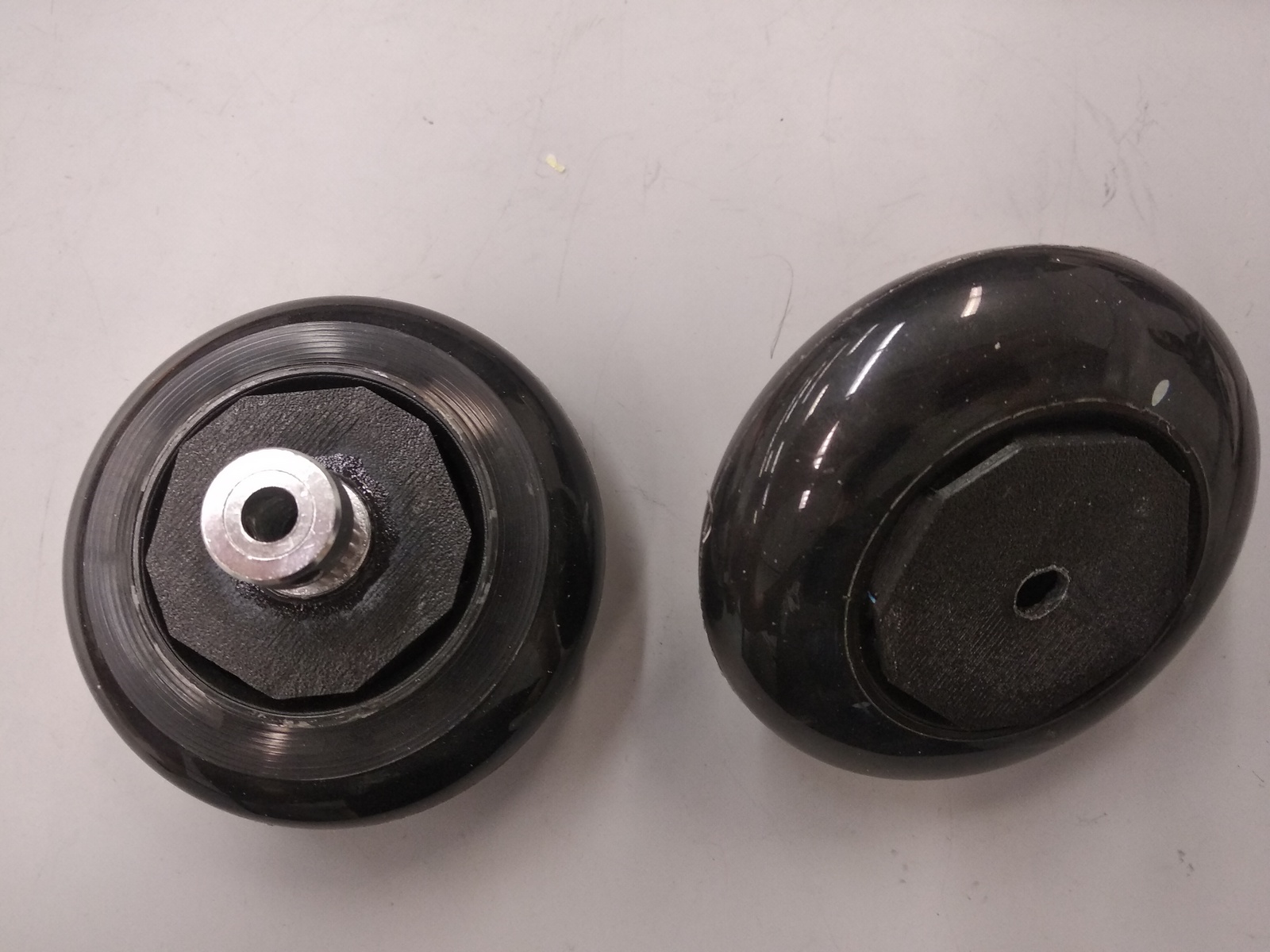
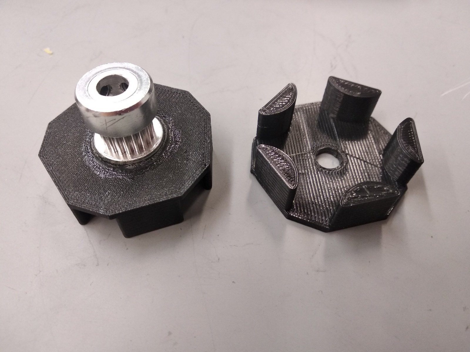
The moving parts consist of skateboard wheels in the front, which are mounted on a simple axle with 3D-printed wheel holders and belt-driven by motors within the chassis body. The hind legs are undriven caster wheels which allow a good degree of movement and reduced the amount of testing needed to calibrate for turning.
Concept sketches of the chassis before it was cut and constructed. As you can see from the sketches, original plans involved motorizing all four legs, but this was dropped due to complexity.
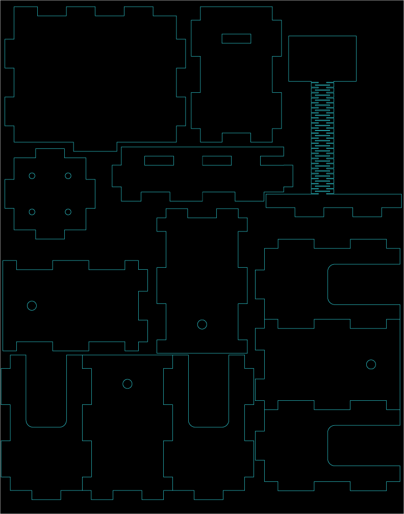
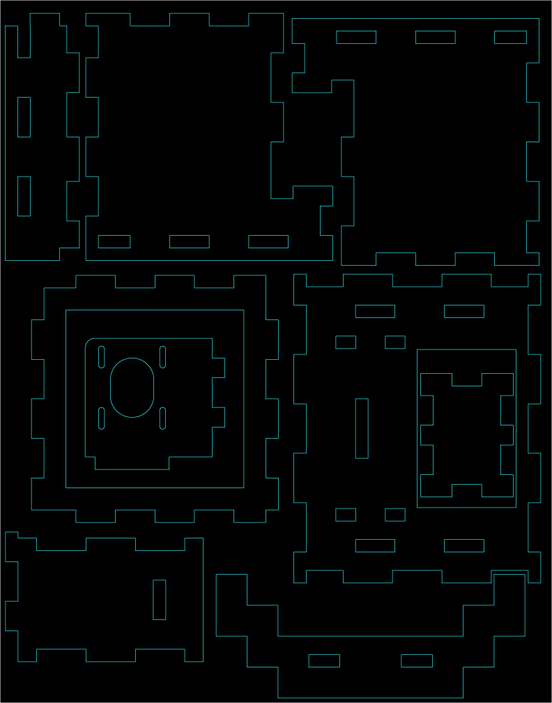
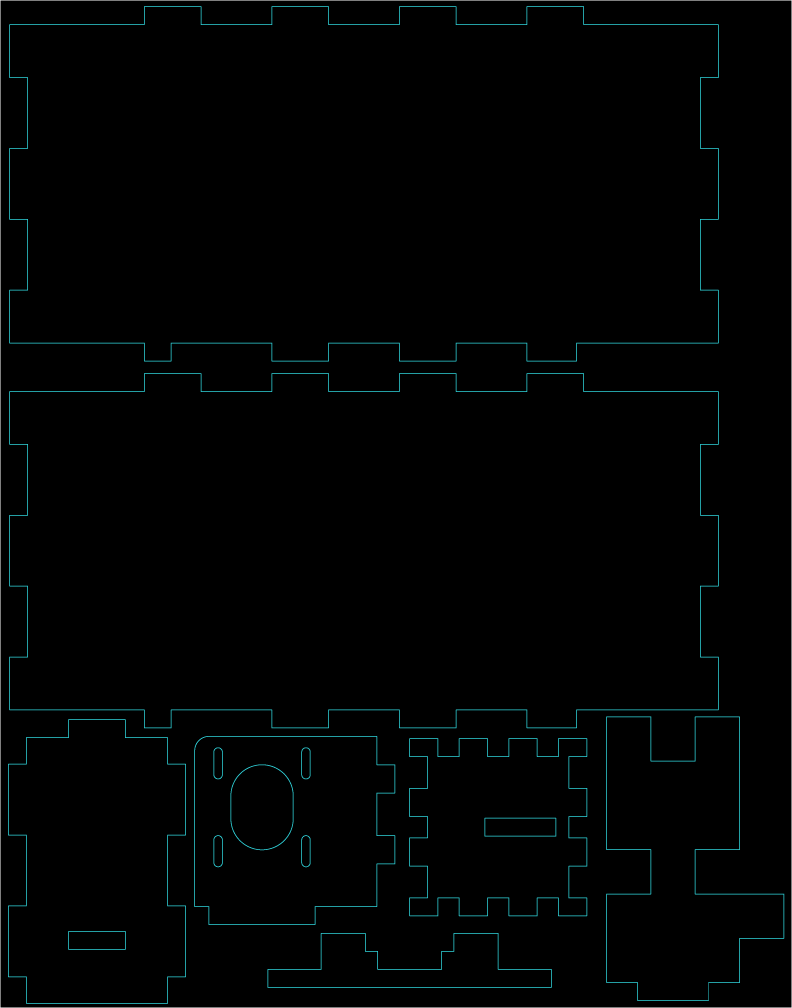
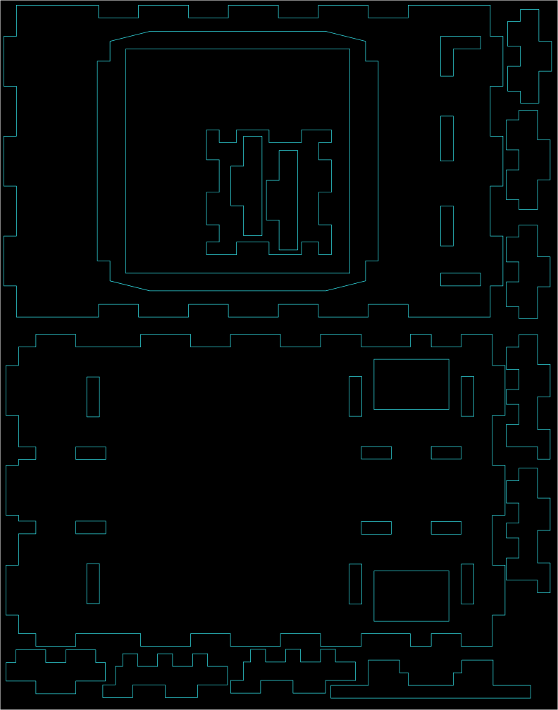
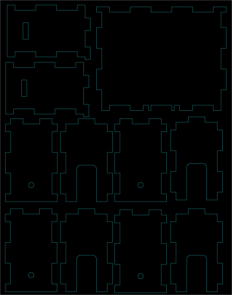
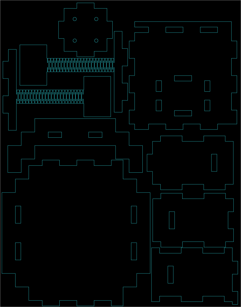
The next step after concept sketches was CAD modeling. Our team chose to use Onshape for its adaptability and ease-of-use. Also included here are the lasercut layout sheets.
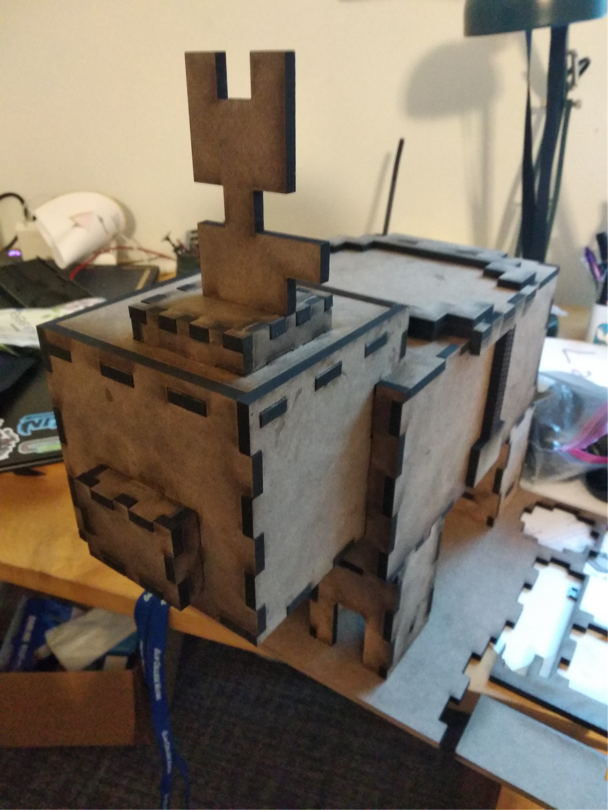
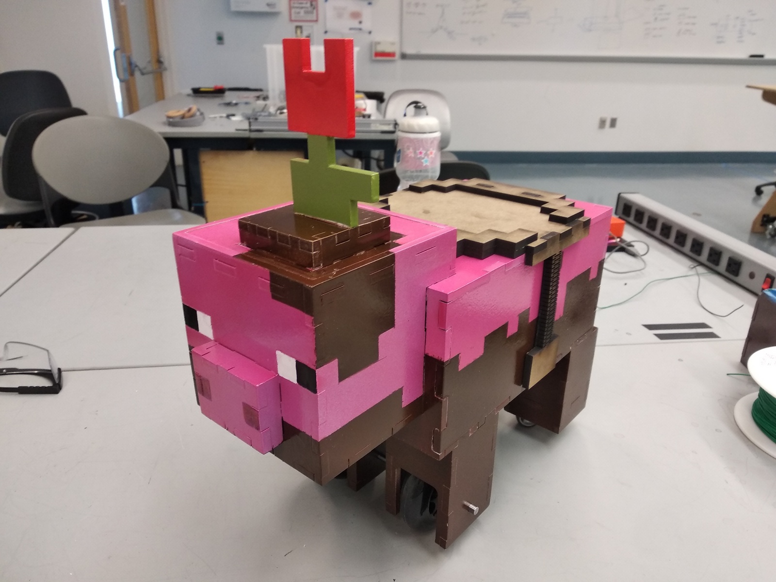
Post lasercutting, we swiftly assembled the chassis using simple wood glue and clamps. You can see the unpainted pig on the left and the final painted chassis on the right. The color scheme was based off of the Minecraft Earth pig, which was an exclusive entity within the app. The skull cap is removable for accessibility, with the flower being a clever disguise for a handle. In addition, the saddle and body side panels are also removable, which allow extensive reach into the body of the pig.
To mount the skateboard wheels, we had to create wheel lock parts so that the entire wheel-axle-belt assembly would turn as one unit. Thus, we modeled this part in Fusion 360 (off of a previous iteration by one of our teammates) to suit our needs. We then superglued the gearing to these parts to finish the constraints.
On the software and firmware side, we used Python to program a simple color-masking algorithm. This is run on a Raspberry Pi 4, which then interfaces with an ArduCam 5 to sense color from a 3D-printed and painted Minecraft-esque carrot object. The Pi then signals the stepper motors via an Arduino and motor shield. To supply power to the Pi, Arduino and motor shield, we have an anchored triple-tap extension cord running from the body of the pig.
The motors used are Nema 17 stepper motors, which are commonly used in 3D printers. These were simply picked because of their availability to us as a team, and the use of other motors is completely viable. We also had the convenience of having the drivers and controllers easily available to us, as well.
Originally, we intended to use computer vision as a means of having the pig interact with its surroundings. We developed a working model, but quickly realized the infeasibility of this method. On a laptop, this algorithm got at best 2 frames per second, which is far slower than would be practical to implement on a Raspberry Pi. Hence we pivoted to a color masking model: our pig would move toward the direction of any orange indicator, such as a carrot. This method was much more reliable in terms of speed, but took measurements so quickly that the bounding boxes we created around orange objects were exceedingly fickle. To counteract the constant fluctuations, we took a moving average of center coordinates and bounding box area to minimize deviation from the mean bounding box. Finally, we encoded "forward" movement as an action taken when the area is sufficiently small, while we assigned "left" and "right" to corrections to the pig's course based on the horizontal distance from the center of the frame. If the pig did not need to turn or move forward, then it would stay in place.
Here we have a demonstration of the color masking algorithm running the motors. As you can see the algorithm detects the color orange and draws a bounding box from which to isolate where the color is located. The field of vision is then divided into five sections, a far left, left, middle, right, and far right area. Where the algorithm detects the carrot is willd determine how hard right or left the pig vehicle will turn, with far left and right areas illiciting a harder pitch towards those directions than left or right, and with center running both motors to go forward.
Some of the Python libraries used in the algorithm are serial, time, math, copy, cv2, and collections.
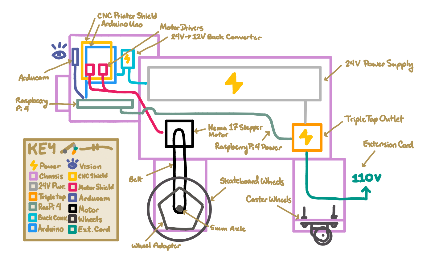
Here you can see our schematic diagram for the electrical system onboard the pig. We utilized an Arduino Uno to control the Nema 17 stepper motors, which was receiving relayed commands from the Raspberry Pi 4 / Arducam setup. We chose the Arduino unit because we had ready access to several Unos and previous experience writing firmware for the system. To interface properly with the steppers, we utilized a CNC Printer Shield coupled with motor drivers, as well.
The Raspberry Pi 4 would run the color-masking program we wrote in Python, and based on input from the Arducam would send signals to move the right, left, or both motors.
To power the Arduino, we had ready access to (as in we previously possessed) a 24V power supply which could directly be plugged into a standard wall outlet. Because the Arduino could not handle the high voltage, we used a buck converter to relay 12V to the device, and a 10 μF capacitor to reduce the amperage as well.
To power the Raspberry Pi, we purchased a dedicated power supply which also would plug into a standard wall outlet.